How do you wire a D-sub connector?
2024-09-21
D-sub connectors, short for D-subminiature connectors, are commonly used in a wide range of applications including computers, communications, and industrial control systems. Whether you're connecting a serial port, VGA display, or custom electronics, knowing how to wire a D-sub connector correctly is crucial for ensuring signal integrity and reliable operation. This guide will take you through the steps of wiring a D-sub connector.
What is a D-Sub Connector?
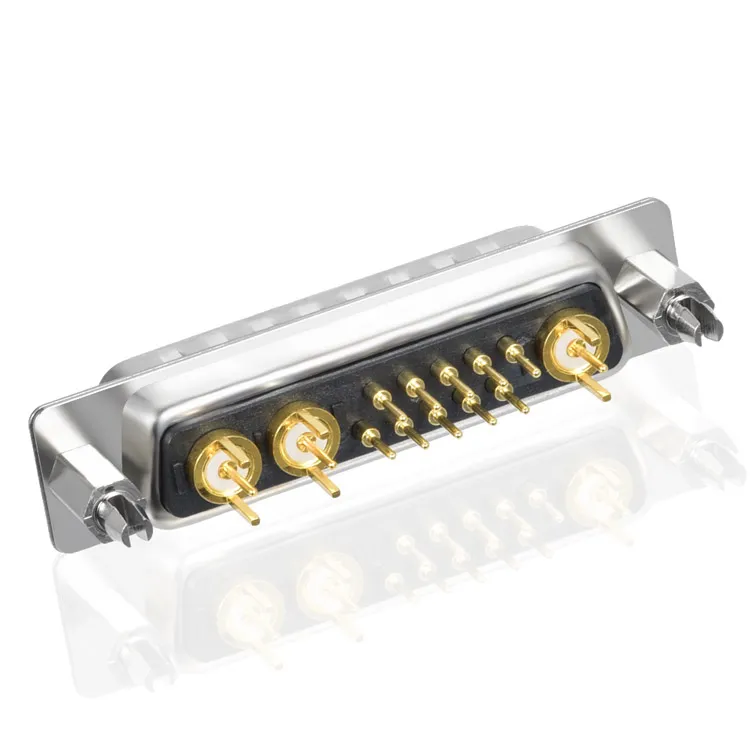
D-sub connectors are characterized by their D-shaped metal shield that provides mechanical support and helps with electromagnetic interference (EMI) protection. They come in various sizes, with different numbers of pins, the most common being:
- DB9 – 9 pins, often used for serial communication (RS-232)
- DB15 – 15 pins, used in VGA connectors
- DB25 – 25 pins, often found in parallel ports or industrial settings
Each D-sub connector is gendered: male connectors (with pins) and female connectors (with sockets). The process of wiring them is similar across all sizes and types.
Materials and Tools You’ll Need
Before starting, gather the following materials and tools:
- D-sub connector (male or female)
- Connector housing (for protection and strain relief)
- Soldering iron and solder (for solder-type connectors)
- Crimping tool (for crimp-type connectors)
- Wire stripper/cutter
- Heat shrink tubing (optional for insulation)
- Multimeter (for testing connectivity)

Step-by-Step Guide to Wiring a D-Sub Connector
1. Identify the Connector Type and Pinout
First, identify the type of D-sub connector you are using and the purpose of each pin. A DB9, for instance, will have different pin configurations than a DB25. The pinout is typically provided in the device's manual or can be found online for standard configurations (e.g., RS-232, VGA).
Tip: You can refer to the manufacturer’s datasheet for the correct pinout if you're unsure. Each pin has a specific function, such as data transmission, ground, or power.
2. Prepare the Wires
- Strip the Wires: Use a wire stripper to remove the insulation from the end of each wire that will be connected to the D-sub. You only need to strip about 1/8 inch (3 mm) of insulation.
- Twist the Wires: If you're working with stranded wire, twist the exposed strands tightly to prevent fraying.
Optional: Slide a piece of heat shrink tubing onto each wire before making connections if you want to ensure insulation between pins later on.
3. Soldering the Wires to a Solder-Type D-Sub Connector
If you're using a solder-type D-sub connector, follow these steps:
- Tin the Wires: Apply a small amount of solder to the exposed wire ends. This process, called tinning, will make it easier to solder the wires to the pins.
- Heat the Pin: Using a soldering iron, heat the appropriate pin on the D-sub connector.
- Attach the Wire: While keeping the pin heated, place the tinned wire onto the pin. Apply a small amount of solder to make the connection.
- Cool and Inspect: Once the solder flows and bonds the wire to the pin, remove the heat and let it cool. Check the connection to ensure it is solid and clean.
Repeat this process for each wire.
4. Crimping the Wires to a Crimp-Type D-Sub Connector
For crimp-style connectors:
- Insert the Wire: Strip the end of the wire, then insert it into the crimp pin or terminal.
- Crimp the Terminal: Use a crimping tool to secure the wire to the pin by pressing down firmly.
- Insert the Pin into the Connector: Once all the wires are crimped, insert each pin into the corresponding slot in the D-sub connector.
Crimping is generally faster than soldering and provides a reliable connection, especially in high-vibration environments.
5. Secure the Connector Housing
Once all the wires are connected, it's time to secure the D-sub connector in its housing. The housing provides strain relief and protects the connector from damage.
- Attach the Housing: Slide the housing over the D-sub connector and secure it in place using the screws provided.
- Strain Relief: Some connector housings include strain relief clamps to hold the cable firmly in place. Tighten these screws to ensure that the wires don’t experience stress if the cable is pulled.
6. Test the Connections
Before using the wired D-sub connector, it's important to test the connections to ensure they are correct and functional.
- Check Continuity: Use a multimeter to test the continuity between the wire and its corresponding pin. This ensures that each pin is properly connected.
- Verify Insulation: Check that no wires or pins are shorting against each other, especially if soldering was used.
If all the connections are correct, the D-sub connector is ready for use.
Tips for Successful D-Sub Wiring
- Double-check your pinout: Before making any connections, ensure that you’re wiring to the correct pins according to the application (e.g., data, power, ground).
- Keep wires short: Avoid leaving excess wire length to minimize the risk of shorts or signal interference.
- Use heat shrink tubing: Heat shrink provides extra protection and insulation between wires.
- Work in a well-ventilated area: If soldering, make sure you have adequate ventilation to avoid inhaling fumes.
Conclusion
Wiring a D-sub connector requires attention to detail and proper technique, but with the right tools and a clear pinout, it can be done efficiently and reliably. Whether you're connecting devices for serial communication or building custom electronics, following the steps outlined above will help you wire a D-sub connector correctly and safely.
SIGNALORIGIN® is the professional d-sub connectors manufacturer, and have got the global recognition. Visit our website at https://www.xhyconn.com to learn more about our products. For inquiries, you can reach us at salesmanager@signalorigin.com.


