Call Us
+86-13544657865
Email Us
salesmanager@signalorigin.com

How to Select D-SUB Connectors: Full Specification Guide for 9Pin / 15Pin / 25Pin / 37Pin
How to Select D-SUB Connectors: Full Specification Guide for 9Pin / 15Pin / 25Pin / 37PinSelecting D-SUB connectors is one of the most frequently asked and error-prone tasks for procurement specialists and hardware engineers. Many teams only discover issues after drawings are finalized: the pin count matches, but the mounting style is wrong; the mounting style is correct, yet the gold plating thickness fails to meet the required mating cycles. The result: samples pass validation while mass production runs into failures. Rework costs far exceed the tiny savings cut from component pricing.
This guide breaks down D-SUB connector selection into five decision dimensions: series, pin count, mounting style, performance grade and reliability metrics. It provides clear checkable criteria for each item, so you can mark requirements directly against your drawing after reading.1. Distinguish the Two Core Series: 1.0 Series vs 0.76 SeriesThe naming of D-SUB series comes from the diameter of male contact pins (the pins that mate with female receptacles):
1.0 Series: male pin diameter = 1.0 mm
0.76 Series: male pin diameter = 0.76 mm
This is the starting point of all selection work.
Important Note: 1.0 / 0.76 refers to the diameter of male pins, NOT the contact pitch.
1.0 Series: contact pitch 2.77 mm, row pitch 2.84 mm
0.76 Series: contact pitch 2.29 mm (15–62Pin) / 2.41 mm (78Pin), row pitch 1.98 mm / 2.08 mm
1.0 Series
Male pin diameter: 1.0 mm; contact pitch 2.77 mm, row pitch 2.84 mm.
Featuring high structural strength and superior current-carrying capacity, it is the mainstream choice for industrial and communication applications.
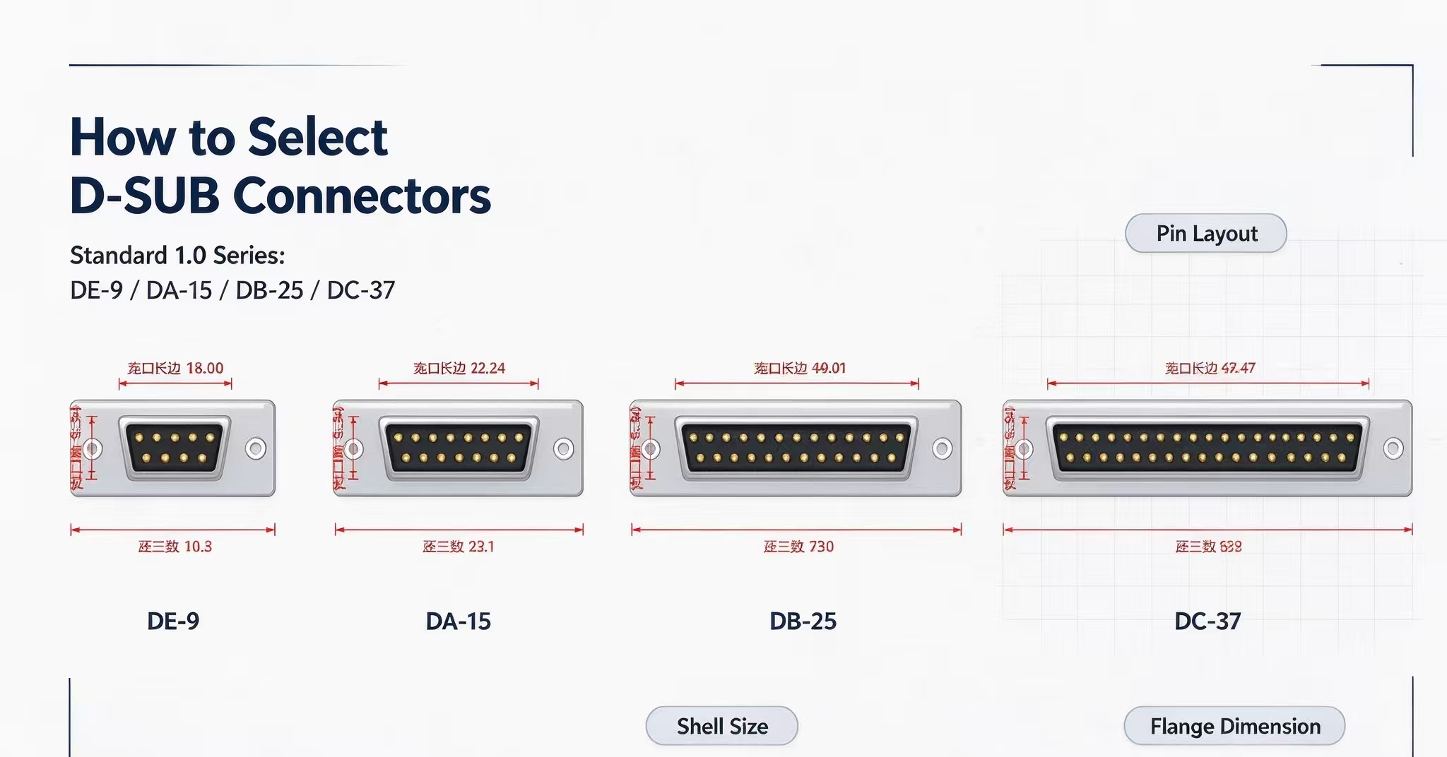
Common layouts: 2-row 9Pin / 15Pin / 25Pin / 37Pin, and 3-row 50Pin.
0.76 Series (High Density)
Male pin diameter: 0.76 mm with finer contacts. Within the same shell size, more signal lines can be arranged.
Common layouts: 3-row 15Pin / 26Pin / 44Pin / 62Pin, and 4-row 78Pin / 100Pin.
Special reminder: The 0.76 series starts at 15Pin (3-row configuration). No 9Pin version is available.
Simple selection rule
Choose the 1.0 Series for low signal count and power transmission scenarios.
Choose the 0.76 Series when you have many signal lines and limited panel space.
If your drawing marks “High Density D-SUB”, it almost always refers to the 0.76 series.2. Pin Count Selection: How to Decide between 9 / 15 / 25 / 37 / 50 PinMore pins do not equal higher reliability. Extra pins raise material cost, increase wiring complexity and occupy more panel cutout space.
Recommended calculation formula:
Total pins = Signal pins + Power pins + 10%–20% spare pins
表格Pin CountTypical Application Notes9PinSerial communication, diagnostic ports, sensor buses. Most widely used, fast lead time and low cost.15PinIndustrial display, VGA-type signals, control board interconnection. Combo versions with power pins are available.25PinParallel communication, multi-channel I/O, PLC expansion. Requires larger panel cutout accordingly.37PinMulti-channel signal acquisition, test equipment, medical devices. Metal shell with locking latches is recommended.50Pin (3-row)High-density signal aggregation, industrial mainboards. Higher mating force; mating operability needs evaluation.3. Mounting Style: Solder Type / Crimp Type / PCB Through-Hole (Straight & Right-Angle)This dimension is often overlooked and is the top cause of mass rework.
Solder Type: Cables are soldered directly to contacts. Low cost and reliable, ideal for small-batch production and harness assembly.
Crimp Type: Wires are crimped into contacts with crimping tools. High efficiency and consistent quality for large-volume harness production. Matching crimp dies are mandatory; mismatched dies will break conductors.
PCB Mount (Straight / Right-Angle 90°): Soldered directly onto PCB.
Straight: for wiring out from the board edge
Right-angle (90°): for side routing to save chassis depth
Critical check items: solder tail length, positioning posts, board edge clearance. A deviation of only 0.2 mm may cause assembly failure.
4. Performance Grade: Standard / High-Current / Combo / Coaxial / WaterproofStandard signal D-SUB contacts have limited current rating. Select upgraded variants for motor, power and RF applications:
High-Current Version: Special contact structure and enhanced plating. Each contact can carry several amps, for power input and servo drives.
Combo (Mixed Layout): Signal contacts and power contacts arranged inside one shell (e.g. 3W3, 5W5). One connector handles both signal and power to reduce interface quantity.
Coaxial RF Version: Integrated coaxial contacts for video, RF and high-speed signals. Impedance consistency and shielding continuity are key.
Waterproof Version: Equipped with sealing gaskets and locking structures. Suitable for outdoor, on-board, marine, mining machinery and washdown / humid environments.
5. Reliability Specifications: 5 Parameters Must Be Specified on Drawings
表格ParameterDescriptionCommon Specification TiersGold Plating ThicknessDetermines oxidation resistance and mating cycle life0.4μm / 0.8μm / 1.27μm and aboveRated CurrentMaximum continuous current per pin~1–3A for standard signal pins; higher for high-current typesContact ResistanceAffects signal integrity and temperature riseTypically milliohm-level and stableMating CyclesPerformance retention after repeated plugging & unpluggingHundreds to thousands of cyclesOperating TemperatureMatches end equipment environment and soldering processIndustrial grade: commonly -40℃ ~ +105℃Domestic D-SUB connectors can now match general models from TE Connectivity, Amphenol and EDAC in these specs, with mechanical and electrical interchangeability for selected parts.
Important: Always run sample validation before replacement, especially for mating force, contact resistance drift and temperature rise. Do not rely solely on datasheet comparison.Workflow Summary: Step-by-Step Selection ChainSeries (1.0 / 0.76) → Pin Count (Signal + Power + Spare) → Mounting Style (Solder / Crimp / PCB) → Performance Grade (Standard / High-Current / Combo / Coaxial / Waterproof) → Reliability Specs (Gold Plating / Current / Cycles / Temp)
Once all five items are confirmed, your D-SUB selection is fully defined for drawings.
Bookmark this guide. After mounting style is confirmed, you may encounter follow-up issues such as crimp die matching, PCB pad design and harness routing. You can come back and check relevant sections by keywords later.✅ SEO Meta Data (for your independent site, ready to use)Meta Title: How to Select D-SUB Connectors | 9Pin 15Pin 25Pin 37Pin Full Selection Guide
Meta Description: Complete D-SUB connector selection guide covering 1.0 & 0.76 high density series, pin count, mounting types, high-current/combo/waterproof options and reliability parameters for industrial hardware engineers & buyers.
Send Inquiry



X
We use cookies to offer you a better browsing experience, analyze site traffic and personalize content. By using this site, you agree to our use of cookies.
Privacy Policy
News
 How to Select D-SUB Connectors: Full Specification Guide for 9Pin / 15Pin / 25Pin / 37Pin2026/10/27
This guide breaks down D-SUB connector selection into five decision dimensions: series, pin count, mounting style, performance grade and reliability metrics. It provides clear checkable criteria for each item, so you can mark requirements directly against your drawing after reading.